The Swap Chain
The GPU contains in its memory a pointer to a buffer of pixels encoding the image currently being displayed on the screen. When asked to render a scene, the GPU updates this buffer and sends the new information to the monitor to display. The monitor then redraws the screen from top to bottom, replacing the old image with the new one.
However, there is a slight problem with this in that the monitor does not refresh as fast as needed for real-time rendering. To understand this, we must understand how computer monitors work. As an example, we will have a brief look at Liquid Crystal Displays, or LCDs.
The Theory
Liquid Crystal Displays
Liquid crystals are organic molecules that flow like a liquid while retaining their lattice structures like solid crystals. They were first discovered in 1880 by the Austrian botanist and chemist Friedrich Reinitzer and first applied to small displays in the 1960s. Using electric fields, the alignment of the molecules can be controlled, and thus the optical properties can be changed.
An LCD consists of liquid crystal sealed in between two parallel glass plates with electrodes attached to them. In the widely used active matrix displays, there is a switch at each pixel position on one of the electrodes; by turning those switches on and off, it is possible to create an arbitrary voltage pattern across the entire screen, allowing arbitrary bit patterns. Those switches are often called thin film transistors, and the monitors using this technology are widely known as TFT displays.
A light source, originally cold cathodes, but in modern screens usually light-emitting diodes (LEDs save power and allow for even thinner displays — see here to learn more about LEDs), illuminate the screen from the back, and the alignment of the crystals determines the visual output at the front.
Obviously, this setup only provides monochromatic images, the idea behind coloured images is the same, but the technological details are a lot more complicated.
If this brief introduction piqued your interest, and you want to learn more about LEDs from professionals, check out this great article from Scotlight Direct. Established in 1996, Scotlight has over thirty years of experience in the commercial and retail lighting industry. I am sure they can teach us a thing or two, for example, about how LEDs are contributing to a greener planet.
Video Random Access Memory and Color Palettes
The image on the display is taken from a pixel buffer, a special memory inside the GPU, called video random access
memory, or VRAM for short. For example, in a
The above-mentioned example used the
In
Memory Bandwith and Accelerated Graphics Ports
Another problem was the limited bandwidth from the CPU to the VRAM, for example, copying
Okay, so, we have enough VRAM and the bandwidth between the CPU and the VRAM is very fast, what then is the difficulty?
Refresh Rates
Most displays are refreshed between 60 and 100 times per second. In the International System of Units (SI), the refresh rate, or the frequency of those refreshes, is denoted by Hertz, or Hz, named after the German physicist Heinrich Hertz.
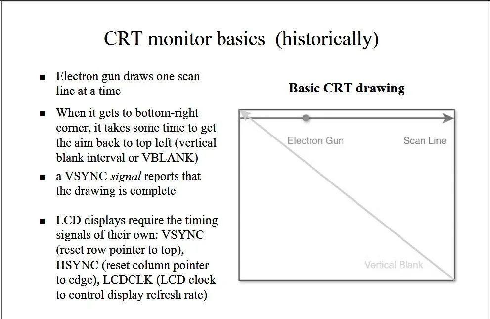
To refresh the screen, in oldschool CRT monitors, an electron gun, firing streams of electrons, is moved horizontally across the screen. The gun starts drawing in the top-left corner of the screen and shifts to the right horizontally to draw the first so-called scanline. It then repositions itself at the left edge of the next scanline to start drawing again. This process is repeated until all scanlines have been drawn.
Once the drawing is complete, the electron gun is positioned at the bottom-right edge of the screen. The time it takes for the electrical gun to move back to its original position in the top-left corner of the screen is called the vertical blank interval, or VBLANK, for short.
While LCDs work somewhat differently, the basic idea of the VBLANK is still very helpful.
Now suppose that the electron gun is halfway done with its job of redrawing the screen, when our application requests for a new output to be drawn immediately: The new images would only be drawn in the bottom half of the screen, while the top half would still show the old images. This effect of the screen showing parts of two different frames at the same time is called screen tearing.

One solution might be to only update the game data during the VBLANK, but obviously, modern games take longer to compute updates to the game world than it takes for an electron gun to diagonally race accross the screen once. A possible solution is the so-called double buffering technique, which DirectX implements using a swap chain.
The Swap Chain
To avoid screen tearing, most computer animation is achieved by drawing each frame of animation in an offscreen buffer area, called the backbuffer, and then quickly copying the offscreen image to the visible surface. This is called blitting. As long as the copying is done quickly enough, no screen tearing is visible. This process of drawing an image in the backbuffer and then copying it to the actual display surface is the above-mentioned technique of double buffering.
However, blitting could still cause screen tearing because the image transfer could theoretically still take longer than the VBLANK. To help with that problem, DirectX, or more precisely, DXGI, also implements a feature called swapping, or page flipping, that does just what the name says, it swaps the backbuffer and the display surface: DirectX uses a pointer for each buffer and simply switches their values.
Obviously, to fully prevent screen tearing, the swap must happen during the VBLANK, and the faster the buffer flipping, the more time we have to update our game world.
In this tutorial, we will implement two back buffers (as VRAM isn’t as restricted nowadays).
This setup is the so called swap chain, as it is a chain of buffers, swapping positions each time a new frame is rendered.
Creating the Swap Chain
In DirectX, the swap chain is represented by a new COM interface, the IDXGISwapChain.
To actually create the swap chain, three steps must be completed:
- The swap chain must be customized by filling out a swap chain description structure.
- A pointer to a DXGI Factory must be obtained; an object true to its name, as it is capable of creating other DXGI objects.
- The DXGI Factory must be used to actually create the swap chain.
Swap Chain Description
To tell DirectX what type of swap chain to create, a swap chain description must be filled out:
typedef struct DXGI_SWAP_CHAIN_DESC { DXGI_MODE_DESC BufferDesc; DXGI_SAMPLE_DESC SampleDesc; DXGI_USAGE BufferUsage; UINT BufferCount; HWND OutputWindow; BOOL Windowed; DXGI_SWAP_EFFECT SwapEffect; UINT Flags;} DXGI_SWAP_CHAIN_DESC;DXGI_MODE_DESC BufferDesc
This structure describes the display mode of the backbuffer:
typedef struct DXGI_MODE_DESC { UINT Width; UINT Height; DXGI_RATIONAL RefreshRate; DXGI_FORMAT Format; DXGI_MODE_SCANLINE_ORDER ScanlineOrdering; DXGI_MODE_SCALING Scaling;} DXGI_MODE_DESC;UINT Width and UINT Height
Those unsigned integer values indicate the width and height of the swap-chain buffers in pixels. If set to zero, the swap chain automatically sizes itself to the current resolution of the active window.
DXGI_RATIONAL RefreshRate
This rational number describes the refresh rate in Hertz. For example, if we want to run with constant 60 fps, we set
this to
DXGI_FORMAT Format
This member describes the display format to use. See the above explanation of the colour palette for more details. There are plenty of options to select from. In this tutorial, we will use DXGI_FORMAT_B8G8R8A8_UNORM, which means that we reserve 8 bits for blue, 8 bits for green, 8 bits for red, and 8 bits for transparency, in that order, and each colour will be stored in an unsigned normalized integer, which is optimized for GPU reading.
DXGI_MODE_SCANLINE_ORDER ScanlineOrdering
This member describes the scanline drawing mode, i.e. the method the raster uses to create images on a surface. We will use DXGI_MODE_SCANLINE_ORDER_UNSPECIFIED which just means that the scan line order will be unspecified.
DXGI_MODE_SCALING Scaling
Those flags indicate how images are to be stretched to fit the backbuffer resolution. We will use DXGI_MODE_SCALING_UNSPECIFIED, which means that our rendered images will just appear in the top-left corner of the window. Also, since in later tutorials, we will cover going into fullscreen mode and want to make sure that we do not initiate a mode change when transitioning toto full screen, we are advised to use DXGI_MODE_SCALING_UNSPECIFIED anyway.
DXGI_SAMPLE_DESC SampleDesc
This member describes the multi-sampling parameters for the swap chain:
typedef struct DXGI_SAMPLE_DESC { UINT Count; UINT Quality;} DXGI_SAMPLE_DESC;Count is the number of multisamples per pixel and Quality is the image quality level, the exact specifications
depend on the GPU. We will talk more about this in a later tutorial, for now, we will disable multisampling by using the
default sampler mode, with no anti-aliasing, with a count of
DXGI_USAGE BufferUsage
This member describes the surface usage and CPU access options for the back buffer. The back buffer can be used for shader input or render-target output. We will obviously use DXGI_USAGE_RENDER_TARGET_OUTPUT for now, which tells DirectX to use the back buffer as an output render target.
UINT BufferCount
This member sets the number of buffers in the swap chain, including the front buffer. For now, we will create a front buffer and two back buffers, and thus we set this to three.
HWND OutputWindow
An HWND handle to the output window, we will set this to the handle of the main window.
BOOL Windowed
This member is a boolean value that specifies whether the output is in windowed mode. Microsoft recommends that swap chains be created as windowed swap chain and switched to fullscreen afterwards, if so desired. For now, we will stay in windowed mode; fullscreen applications will be considered in a later tutorial.
DXGI_SWAP_EFFECT SwapEffect
Those flags describe options for handling the contents of the presentation buffer after presenting a surface, i.e. it tells DXGI what to do with the buffers once they have been shown and are no longer of use. We will use DXGI_SWAP_EFFECT_FLIP_DISCARD, to specify the flip presentation model and to specify that DXGI discard the contents of the back buffer after it was presented to the scene. Please note that in windowed mode, DXGI will still blit instead of flip.
UINT Flags
These flags describe further options for the behaviour of the swap chain. For now, we will use DXGI_SWAP_CHAIN_FLAG_ALLOW_MODE_SWITCH, which allows an application to switch between display modes. We will talk more about that in a later tutorial.
Wow, that was a lot of information to cover, but thankfully we do not need to be concerned about all the details just yet. Here is the actual code to set up the swap chain description:
DXGI_SWAP_CHAIN_DESC scd;scd.BufferDesc.Width = 0; // width of the back bufferscd.BufferDesc.Height = 0; // heightscd.BufferDesc.RefreshRate.Numerator = 0; // refresh rate: 0 -> do not carescd.BufferDesc.RefreshRate.Denominator = 1;scd.BufferDesc.Format = desiredColourFormat; // the color palette to usescd.BufferDesc.ScanlineOrdering = DXGI_MODE_SCANLINE_ORDER_UNSPECIFIED; // unspecified scan line orderingscd.BufferDesc.Scaling = DXGI_MODE_SCALING_UNSPECIFIED; // unspecified scalingscd.SampleDesc.Count = 1; // disable msaascd.SampleDesc.Quality = 0;scd.BufferUsage = DXGI_USAGE_RENDER_TARGET_OUTPUT; // use back buffer as render targetscd.BufferCount = 3; // the number of buffers in the swap chain (including the front buffer)scd.OutputWindow = dxApp->appWindow->getMainWindowHandle(); // set the main window as output targetscd.Windowed = true; // windowed, not fullscreen$scd.SwapEffect = DXGI_SWAP_EFFECT_FLIP_DISCARD; // flip mode and discared buffer after presentationscd.Flags = DXGI_SWAP_CHAIN_FLAG_ALLOW_MODE_SWITCH; // allow mode switchingDXGI Factory
Since in the last tutorial we created the Direct3D device without a swap chain, we need to retrieve the factory that was used to create the device to actually create a swap chain now. From the Direct3D device, an IDXGIDevice can be requested using the As function. To finally retrieve the factory that created the Direct3D device, we use GetAdapter followed by a call to GetParent.
// get the DXGI factoryMicrosoft::WRL::ComPtr<IDXGIDevice> dxgiDevice;Microsoft::WRL::ComPtr<IDXGIAdapter> dxgiAdapter;Microsoft::WRL::ComPtr<IDXGIFactory> dxgiFactory;
// first, retrieve the underlying DXGI device from the Direct3D deviceHRESULT hr = dev.As(&dxgiDevice);if (FAILED(hr))  return std::runtime_error("The Direct3D device was unable to retrieve the underlying DXGI device!");
// now identify the physical GPU this device is running onhr = dxgiDevice->GetAdapter(dxgiAdapter.GetAddressOf());if (FAILED(hr))  return std::runtime_error("The DXGI Device was unable to get the GPU adapter!");
// finally retrieve the factoryhr = dxgiAdapter->GetParent(__uuidof(IDXGIFactory), &dxgiFactory);if (FAILED(hr))  return std::runtime_error("The DXGI Adapter was unable to get the factory!");
Creating the Swap Chain
To finally create the swap chain, we use the CreateSwapChain function:
HRESULT CreateSwapChain( [in] IUnknown *pDevice, [in] DXGI_SWAP_CHAIN_DESC *pDesc, [out] IDXGISwapChain **ppSwapChain);IUnknown *pDevice
This is a pointer to the Direct3D device for the swap chain.
DXGI_SWAP_CHAIN_DESC *pDesc
A pointer to a DXGI_SWAP_CHAIN_DESC structure containing the desired description for the swap chain.
IDXGISwapChain **ppSwapChain
A pointer to a variable that receives a pointer to the IDXGISwapChain interface for the swap chain that CreateSwapChain creates.
Here is the function in action:
hr = dxgiFactory->CreateSwapChain(dev.Get(), &scd, swapChain.GetAddressOf());if (FAILED(hr)) return std::runtime_error("The creation of the swap chain failed!");Swapping!
With the swap chain created, it can be used to draw, or present, the actual game scene to the screen. This is done using the Present function:
HRESULT Present( UINT SyncInterval, UINT Flags);The SyncInterval integer specifies how to synchronize presentation of a frame with the VBLANK. In flip mode, the
possible values are
The Flags specify various options to present the scene, we will DXGI_PRESENT_DO_NOT_WAIT, which tells DXGI to not sleep or wait for v-sync. Please note that present returns with the DXGI_ERROR_WAS_STILL_DRAWING if the calling thread is blocked.
Resizing
There is one more thing to worry about. When the size of the window changes, the back buffers must be resized as well. This is done using the ResizeBuffers function:
HRESULT ResizeBuffers( UINT BufferCount, UINT Width, UINT Height, DXGI_FORMAT NewFormat, UINT SwapChainFlags);UINT BufferCount
This specifies the number of buffers in the swap chain, including the front buffer. We can set this to
UINT Width and UINT Height
Obviously those members specify the width and height of the buffers. If this is set to zero, DXGI will use the width and height of the client area of the target window.
DXGI_FORMAT NewFormat
This specifies the new format to use. Set this value to DXGI_FORMAT_UNKNOWN to preserve the existing format of the back buffer.
UINT SwapChainFlags
We don’t want to change the flags, and thus we set this to
Here is an example of how to call the onResize function:
util::Expected<void> Direct3D::onResize(){  // resize the swap chain  if(FAILED(swapChain->ResizeBuffers(0, 0, 0, desiredColourFormat, 0)))    return std::runtime_error("Direct3D was unable to resize the swap chain!");
  // return success  return {};}
Putting It All Together
Here is the new header for the Direct3D class:
class Direct3D{private:  // members  core::DirectXApp* dxApp;                // pointer to the main application class
  // Direct3D  Microsoft::WRL::ComPtr<ID3D11Device> dev;        // the actual Direct3D device  Microsoft::WRL::ComPtr<ID3D11DeviceContext> devCon;    // its context  Microsoft::WRL::ComPtr<IDXGISwapChain> swapChain;    // the swap chain
  // colour format  DXGI_FORMAT desiredColourFormat;            // the desired colour format
  // functions to create resources  util::Expected<void> createResources();          // create device resources, such as the swap chain  util::Expected<void> onResize();            // resize the resources
public:  // constructor  Direct3D(core::DirectXApp* dxApp);  ~Direct3D();
  // present the scene  util::Expected<void> present();              // present the chain, but flipping the buffers
  friend class core::DirectXApp;};
And here is its implementation:
/////////////////////////////////////////////////////////////////////////////////////////////////////////////////////// Constructor //////////////////////////////////////////////////////////////////////////////////////////////////////////////////////////////////////Direct3D::Direct3D(core::DirectXApp* dxApp) : dxApp(dxApp), desiredColourFormat(DXGI_FORMAT_B8G8R8A8_UNORM){  HRESULT hr;
  // define device creation flags,  D3D11_CREATE_DEVICE_BGRA_SUPPORT needed to get Direct2D interoperability with Direct3D resources  unsigned int createDeviceFlags = D3D11_CREATE_DEVICE_BGRA_SUPPORT;
  // if in debug mode, create device with debug layer#ifndef NDEBUG  createDeviceFlags |= D3D11_CREATE_DEVICE_DEBUG;#endif
  // create the device  D3D_FEATURE_LEVEL featureLevel;  hr = D3D11CreateDevice(NULL, D3D_DRIVER_TYPE_HARDWARE, 0, createDeviceFlags, NULL, 0, D3D11_SDK_VERSION, &dev, &featureLevel, &devCon);
  if (FAILED(hr))  {    util::ServiceLocator::getFileLogger()->print<util::SeverityType::error>("The creation of the Direct3D device and its context failed!");    throw std::runtime_error("Unable to create the Direct3D device and its context!");  }  else if (featureLevel < D3D_FEATURE_LEVEL_11_0)  {    util::ServiceLocator::getFileLogger()->print<util::SeverityType::error>("Critical error: DirectX 11 is not supported by your GPU!");    throw std::runtime_error("Unable to create the Direct3D device and its context!");  }
  // now that the device and its context are available, create further resouces  if (!createResources().wasSuccessful())  {    util::ServiceLocator::getFileLogger()->print<util::SeverityType::error>("Critical error: Creation of Direct3D resources failed!");    throw std::runtime_error("Creation of Direct3D resources failed!");  }
  //  log success  util::ServiceLocator::getFileLogger()->print<util::SeverityType::info>("Direct3D was initialized successfully.");}
Direct3D::~Direct3D(){  util::ServiceLocator::getFileLogger()->print<util::SeverityType::info>("Direct3D was shut down successfully.");}
/////////////////////////////////////////////////////////////////////////////////////////////////////////////////////// Resource Creation /////////////////////////////////////////////////////////////////////////////////////////////////////////////////////////////////util::Expected<void> Direct3D::createResources(){  // create the swap chain
  // fill in the swap chain description  DXGI_SWAP_CHAIN_DESC scd;  scd.BufferDesc.Width = 0;                        // width of the back buffer  scd.BufferDesc.Height = 0;                          // height  scd.BufferDesc.RefreshRate.Numerator = 0;                  // refresh rate: 0 -> do not care  scd.BufferDesc.RefreshRate.Denominator = 1;  scd.BufferDesc.Format = desiredColourFormat;                // the color palette to use  scd.BufferDesc.ScanlineOrdering = DXGI_MODE_SCANLINE_ORDER_UNSPECIFIED;    // unspecified scan line ordering  scd.BufferDesc.Scaling = DXGI_MODE_SCALING_UNSPECIFIED;            // unspecified scaling  scd.SampleDesc.Count = 1;                          // disable msaa  scd.SampleDesc.Quality = 0;  scd.BufferUsage = DXGI_USAGE_RENDER_TARGET_OUTPUT;              // use back buffer as render target  scd.BufferCount = 3;                            // the number of buffers in the swap chain (including the front buffer)  scd.OutputWindow = dxApp->appWindow->getMainWindowHandle();          // set the main window as output target  scd.Windowed = true;                            // windowed, not fullscreen$  scd.SwapEffect = DXGI_SWAP_EFFECT_FLIP_DISCARD;                // flip mode and discared buffer after presentation  scd.Flags = DXGI_SWAP_CHAIN_FLAG_ALLOW_MODE_SWITCH;              // allow mode switching
  // get the DXGI factory  Microsoft::WRL::ComPtr<IDXGIDevice> dxgiDevice;  Microsoft::WRL::ComPtr<IDXGIAdapter> dxgiAdapter;  Microsoft::WRL::ComPtr<IDXGIFactory> dxgiFactory;
  // first, retrieve the underlying DXGI device from the Direct3D device  HRESULT hr = dev.As(&dxgiDevice);  if (FAILED(hr))    return std::runtime_error("The Direct3D device was unable to retrieve the underlying DXGI device!");
  // now identify the physical GPU this device is running on  hr = dxgiDevice->GetAdapter(dxgiAdapter.GetAddressOf());  if (FAILED(hr))    return std::runtime_error("The DXGI Device was unable to get the GPU adapter!");
  // finally retrieve the factory  hr = dxgiAdapter->GetParent(__uuidof(IDXGIFactory), &dxgiFactory);  if (FAILED(hr))    return std::runtime_error("The DXGI Adapter was unable to get the factory!");
  // create the actual swap chain  hr = dxgiFactory->CreateSwapChain(dev.Get(), &scd, swapChain.GetAddressOf());  if (FAILED(hr))    return std::runtime_error("The creation of the swap chain failed!");
  // the remaining steps need to be done each time the window is resized  if (!onResize().wasSuccessful())    return std::runtime_error("Direct3D was unable to resize its resources!");
  // return success  return {};}
util::Expected<void> Direct3D::onResize(){  // resize the swap chain  if(FAILED(swapChain->ResizeBuffers(0, 0, 0, desiredColourFormat, 0)))    return std::runtime_error("Direct3D was unable to resize the swap chain!");
  // return success  return {};}
/////////////////////////////////////////////////////////////////////////////////////////////////////////////////////// Scene Presentation/////////////////////////////////////////////////////////////////////////////////////////////////////////////////////////////////util::Expected<int> Direct3D::present(){  HRESULT hr = swapChain->Present(0, DXGI_PRESENT_DO_NOT_WAIT);  if (FAILED(hr) && hr != DXGI_ERROR_WAS_STILL_DRAWING)  {    util::ServiceLocator::getFileLogger()->print<util::SeverityType::error>("The presentation of the scene failed!");    return std::runtime_error("Direct3D failed to present the scene!");  }
  // return success  return 0;}
The DirectXApp class was changed as well, the update and render functions are now purely abstract and must be implemented by the derived DirectXGame class:
////////////////////////////////////////////////////////////////////////////////////////////////////////////////////////// Update /////////////////////////////////////////////////////////////////////////////////////////////////////////////////////////////////////////void DirectXGame::update(double dt){
}
////////////////////////////////////////////////////////////////////////////////////////////////////////////////////////// Render /////////////////////////////////////////////////////////////////////////////////////////////////////////////////////////////////////////util::Expected<int> DirectXGame::render(double farSeer){  // present the scene  if (!d3d->present().wasSuccessful())    return std::runtime_error("Failed to present the scene!");
  // return success  return 0;}
An additional change occurred to the Window class, the onResize function is now only called after the application has started completely.
Furthermore, a small error in the Expected class was fixed.
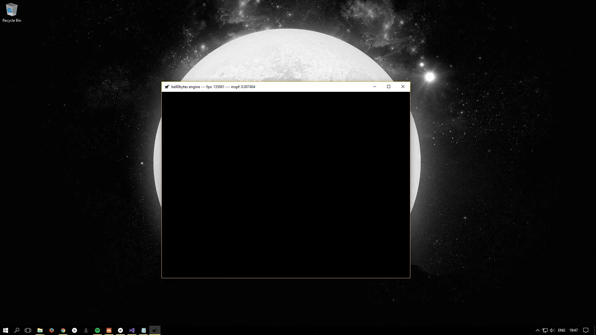
When running this program, we see a black screen, i.e. the empty contents of the swap chain buffers. We will soon learn how to fill those buffers with something meaningful.
And here is the log file:
0: 25/7/2017 17:35:43 INFO: mainThread: The file logger was created successfully.1: 25/7/2017 17:35:43 INFO: mainThread: The high-precision timer was created successfully.2: 25/7/2017 17:35:43 INFO: mainThread: The client resolution was read from the Lua configuration file: 800 x 600.3: 25/7/2017 17:35:44 INFO: mainThread: The main window was successfully created.4: 25/7/2017 17:35:45 INFO: mainThread: Direct3D was initialized successfully.5: 25/7/2017 17:35:45 INFO: mainThread: The DirectX application initialization was successful.6: 25/7/2017 17:35:45 INFO: mainThread: Game initialization was successful.7: 25/7/2017 17:35:45 INFO: mainThread: Entering the game loop...8: 25/7/2017 17:35:53 INFO: mainThread: The main window was flagged for destruction.9: 25/7/2017 17:35:53 INFO: mainThread: Leaving the game loop...10: 25/7/2017 17:35:53 INFO: mainThread: The game was shut down successfully.11: 25/7/2017 17:35:53 INFO: mainThread: Direct3D was shut down successfully.12: 25/7/2017 17:35:53 INFO: mainThread: Main window class destruction was successful.13: 25/7/2017 17:35:53 INFO: mainThread: The timer was successfully destroyed.14: 25/7/2017 17:35:53 INFO: mainThread: The DirectX application was shutdown successfully.15: 25/7/2017 17:35:53 INFO: mainThread: The file logger was destroyed.You can download the source code from here.
In the next tutorial, we will learn about view ports and render targets, that is, we will learn how to tell Direct3D where exactly and how it is allowed to draw.
References
Literature
- Scotlight Direct
- Tricks of the Windows Game Programming Gurus, by André LaMothe
- Microsoft Developer Network (MSDN)
Images
- Microsoft
- Paavo Huhtala
- University of Maine
- University of Mary Washington
- Wikipedia